Protect Analog Circuit in Data Logger Module PCB Reverse Engineering
The best ways to protect sensitive analog circuits from being affected by fast logic are to physically separate the two by the Data Logger Module PCB Reverse Engineering, and to use no faster logic family than is dictated by system requirements. In some cases, this may require the use of several logic families in a system.
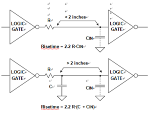
An alternative is to use series resistance or ferrite beads to slow down the logic transitions where highest speed isn’t required. Below Figure shows two methods.

Damping Resistors Slow Down Fast Logic Edges to Minimize EMI-RFI Problems with Data Logger Module PCB Reverse Engineering
In the first, the series resistance and the input capacitance of the gate form a low-pass filter. Typical CMOS input capacitance is 5 pF to10 pF. Locate the series resistor close to the driving gate. The resistor minimizes transient currents and may eliminate the necessity of using transmission line techniques.
The value of the resistor should be chosen such that the rise and fall times at the receiving gate are fast enough to meet system requirement, but no faster. Also, make sure that the resistor is not so large that the logic levels at the receiver are out of specification because of the voltage drop caused by the source and sink current which flow through the resistor.
The second method is suitable for longer distances (>2 inches), where additional capacitance is added to slow down the edge speed. Notice that either one of these techniques increases delay and increases the rise/fall time of the original signal. This must be considered with respect to the overall timing budget, and the additional delay may not be acceptable.


