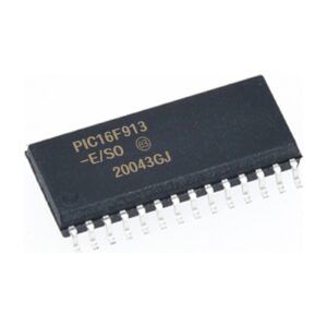
Crack Microchip Microcontroller PIC16F913 Flash Memory and readout embedded firmware from MCU PIC16F913, and clone the binary or heximal file to new PIC16F913 processor to realize the purpose of cloning PCI slot card printed circuit board;

Crack Microchip Microcontroller PIC16F913 Flash Memory and readout embedded firmware from MCU PIC16F913, and clone the binary or heximal file to new PIC16F913 processor to realize the purpose of cloning PCI slot card printed circuit board;
Clock source modes can be classified as external or internal.
External clock modes rely on external circuitry for the clock Examples are oscillator modules (EC mode), quartz crystal resonators or ceramic resonators (LP, XT and HS modes), and Resistor-Capacitor (RC mode) circuits. Internal clock sources are contained internally within the PIC16F913. The PIC16F913 has two internal oscillators: the 8 MHz High-Frequency Internal Oscillator (HFINTOSC) and 31 kHz Low-Frequency Internal Oscillator (LFINTOSC).

şifreli Mikroçip mikrodenetleyicisini PIC16F913 kırmak, flash bellek içeriğini çıkarmak ve kilitli MCU PIC16F913’den ikili programın gömülü bellenimini veya onaltılık verileri okumak için koruyucu sigorta bitini kırmak ve PCI slot kartı baskılı devre kartını klonlama amacını gerçekleştirmek için ikili veya onaltılık dosyayı yeni PIC16F913 mikroişlemciye klonlamak;
The system clock can be selected between external or internal clock sources via the System Clock Selection (SCS) bit (see Section 3.5 “Clock Switching”). If the PIC16F913 is configured for LP, XT or HS modes, the Oscillator Start-up Timer (OST) counts 1024 oscil- lations from the OSC1 pin, following a Power-on Reset (POR) and the Power-up Timer (PWRT) has expired (if configured), or a wake-up from Sleep. During this time, the program counter does not increment and program execution is suspended when reverse engineering high speed digital signal pcb board.

الكراك المشفرة Microchip متحكم PIC16F913 بت الصمامات الواقية لاستخراج محتوى ذاكرة الفلاش وقراءة البرامج الثابتة المضمنة للبرنامج الثنائي أو البيانات السداسية من PIC16F913 MCU المقفل ، واستنساخ الملف الثنائي أو السداسي إلى معالج دقيق جديد PIC16F913 لتحقيق الغرض من استنساخ لوحة الدوائر المطبوعة لبطاقة فتحة PCI ؛
The OST ensures that the oscillator circuit, using a quartz crystal resonator or ceramic resonator, has started and is providing a stable system clock to the PIC16F688. When switching between clock sources a delay is required to allow the new clock to stabilize. These oscillator delays are shown in Table 3-1.
In order to minimize latency between external oscillator start-up and code execution, the Two-Speed Clock Start-up mode can be selected (see Section 3.6 “Two-Speed Clock Start-up Mode”).


