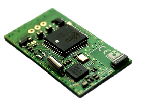
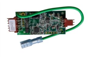
Copying Heart Rate Monitor PCB Board Schematic needs to choose the correct grid set and always use grid spacing that matches most components. Although the practicality of multi-grid may seem important, if engineers can think more about the early stages of PCB layout design when cloning, they can avoid the difficulty of spacing setting and maximize the application of the printed circuit board.

Copying Heart Rate Monitor PCB Board Schematic diagram, gerber file, bom list and layout
Since Heart Rate Monitor PCB Boards use multiple package sizes, engineers should use the Heart Rate Monitor that best suits their design. Also, polygons are very important for copper plating on circuit boards. Polygon fill bias is often seen when copper-plating polygons on multi-gate boards. While it does not have a single grid-based standard, it can provide service beyond the required service life of the Heart Rate Monitor PCB Board.

Heart Rate Monitor PCB Board Schematic reverse engineering
Keep the path the shortest and most direct. It sounds simple and common, but it should be kept in mind at every stage, even if it means changing the pcb board layout to optimize trace lengths. This is especially true for analog and high-speed digital circuit board reverse engineering, where system performance is always partially limited by impedance and parasitics;


