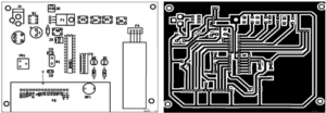
When we Copy PCB Board Layout Diagram, the lines are exquisite: the conditional wide line is never made fine; the high voltage and high frequency lines should be smooth, no sharp chamfers, and corners should not be used. The ground wire should be as wide as possible. It is best to use a large area of copper, which has a considerable improvement on the grounding point problem.
Some problems occur in post-production, but they are brought about by PCB board design. They are: too many hole holes, and the copper sinking process will cause hidden dangers. Therefore, the design should minimize the number of holes which can be done in the process of Copy PCB Board Layout Diagram. Straight lines in the same direction are too dense, and it is easy to form a piece when welding.

Copy PCB Board Layout Diagram
Therefore, the line density should be determined by the level of the welding process. The distance between the solder joints is too small, which is not conducive to manual soldering, and can only solve the welding quality by reducing the work efficiency. Otherwise it will leave hidden dangers. Therefore, the determination of the minimum distance of the solder joint should take into account the quality and work efficiency of the welding personnel.
The pad or via hole size is too small, or the pad size is not properly matched to the hole size. The former is not good for manual drilling, and the latter is not good for CNC drilling. It is easy to drill the pad into a “c” shape and drill the pad again. The wire is too thin, and the large area of the unwiring area is not provided with copper, which is likely to cause uneven corrosion. That is, when the unwiring area is corroded, the thin wire is likely to corrode too much, or it may be broken or completely broken.
Therefore, the role of setting copper is not only to increase the ground area and anti-interference. Many of these factors will greatly reduce the quality of the PCB board and the reliability of future products.


