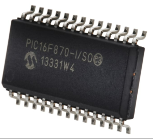
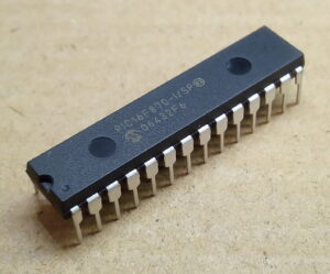
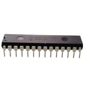
Copy Microchip PIC16F870 Microcontroller Flash Binary needs to unlock encrypted MCU PIC16f870 protective fuse bit, and then reverse engineering pcb card for its schematic diagram, layout and gerber file;

Copy Microchip PIC16F870 Microcontroller Flash Binary needs to unlock encrypted MCU PIC16f870 protective fuse bit, and then reverse engineering pcb card for its schematic diagram, layout and gerber file;
The External Clock (EC) mode allows an externally generated logic level as the system clock source. When operating in this mode, an external clock source is connected to the OSC1 pin and the RA5 pin is available for general purpose I/O. Figure 3-2 shows the pin connections for EC mode.
The Oscillator Start-up Timer (OST) is disabled when EC mode is selected. Therefore, there is no delay in operation after a Power-on Reset (POR) or wake-up from Sleep. Because the PIC16F688 design is fully static, stopping the external clock input will have the effect of halting the device while leaving all data intact. Upon restarting the external clock, the device will resume operation as if no time had elapsed to help recovering pcb board schematic diagram.

kopyalama Microchip güvenli PIC16F870 mikrodenetleyici flash ikili dosyası ve eeprom onaltılık verilerinin şifreli MCU PIC16f870 koruyucu sigorta bitinin kilidini açması gerekir, şifreli mikroişlemci PIC16F870 gömülü bellenimi çıkarın ve ardından şematik diyagramı, düzeni ve gerber dosyası için baskılı devre kartını tersine mühendislik yapın;
The LP, XT and HS modes support the use of quartz crystal resonators or ceramic resonators connected to the OSC1 and OSC2 pins (Figure 3-1). The mode selects a low, medium or high gain setting of the internal inverter-amplifier to support various resonator types and speed.
LP Oscillator mode selects the lowest gain setting of the internal inverter-amplifier. LP mode current con- sumption is the least of the three modes. This mode is best suited to drive resonators with a low drive level specification, for example, tuning fork type crystals.
XT Oscillator mode selects the intermediate gain setting of the internal inverter-amplifier. XT mode cur- rent consumption is the medium of the three modes. This mode is best suited to drive resonators with a medium drive level specification, for example, low-frequency/AT-cut quartz crystal resonators.

نسخة رقاقة مؤمنة PIC16F870 ملف ثنائي فلاش متحكم وبيانات eeprom heximal يحتاج إلى فتح بت الصمامات الواقية MCU PIC16f870 المشفرة ، واستخراج البرامج الثابتة المضمنة من PIC16F870 المعالجات الدقيقة المشفرة ثم عكس الهندسة المطبوعة لوحة الدوائر لمخططها التخطيطي والتخطيط وملف جربر ؛
HS Oscillator mode selects the highest gain setting of the internal inverter-amplifier. HS mode current consumption is the highest of the three modes. This mode is best suited for resonators that require a high drive setting, for example, high-frequency/AT-cut quartz crystal resonators or ceramic resonators.
Figure 3-3 and Figure 3-4 show typical circuits for quartz crystal and ceramic resonators, respectively.


