Most ADC, DAC, and other mixed-signal device data sheets discuss grounding relative to Cooling System PCB Board Reverse Engineering, usually the manufacturer’s own evaluation board. This has been a source of confusion when trying to apply these principles to multicard or multi-ADC/DAC systems.
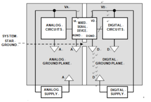
The recommendation is usually to split the PCB ground plane into an analog plane and a digital plane. It is then further recommended that the AGND and DGND pins of a converter be tied together and that the analog ground plane and digital ground planes be connected at that same point as shown in Figure 12.56. This essentially creates the system “star” ground at the mixed-signal device.

Mixed Signal Grounding in Cooling System PCB Board Reverse Engineering
All noisy digital currents flow through the digital power supply to the digital ground plane and back to the digital supply; they are isolated from the sensitive analog portion of the board. The system star ground occurs where the analog and digital ground planes are joined together at the mixed signal device.
While this approach will generally work in a simple system with a single PCB and single ADC/DAC, it is not optimum for multicard mixed-signal systems. In systems having several ADCs or DACs on different PCBs (or on the same PCB, for that matter), the analog and digital ground planes become connected at several points, creating the possibility of ground loops and making a single- point “star” ground system impossible.
For these reasons, this grounding approach is not recommended for multicard systems, and the approach previously discussed should be used for mixed-signal ICs with low digital currents.


