The main function of the component pin connection module is to help the user to edit the connection information between components with an intuitive and convenient interface, and to store the relevant data of the component in the database of the server, as a result of that, engineer specified for PCB reverse engineering need to research and develop Component Connection Processing Graphic Symbol Design to facilitate the process.

The data table is obtained from these data to generate a schematic diagram. When the components are arranged, there are both bitmaps and vector graphics. The component placement module is a computer-aided software module that combines graphics and images and has database technology.
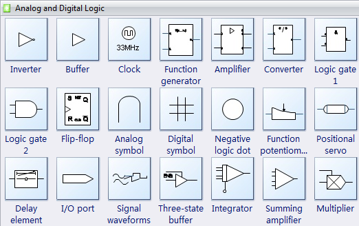
In order to visually reflect the analysis, operation and running status of the system, some basic display and operation functions can be realized on the Component Connection Processing Graphic Symbol Design. Display the operating parameters of the system in the appropriate position, you can graphically display the operating status of some devices. Any circuit diagram is made up of several electrical symbols with certain meanings, which are connected by wires according to certain rules.

Components are the basic elements of a circuitry schematic diagram. Component symbols are an important part of a circuit diagram. They are used to represent different types and functions, and have an irreplaceable role in expressing the functions of circuit diagrams of Printed circuit board.
The symbolic drawings of electrical components are composed of limited electrical symbols, and the relevant parts of the national markings have clear provisions on the drawing and symbolic meanings of various electrical component symbols.
However, there are many types of electrical components, and the models are different. Even for similar components, products of different manufacturers have no uniform model and structure, and the replacement of electrical components is very fast.
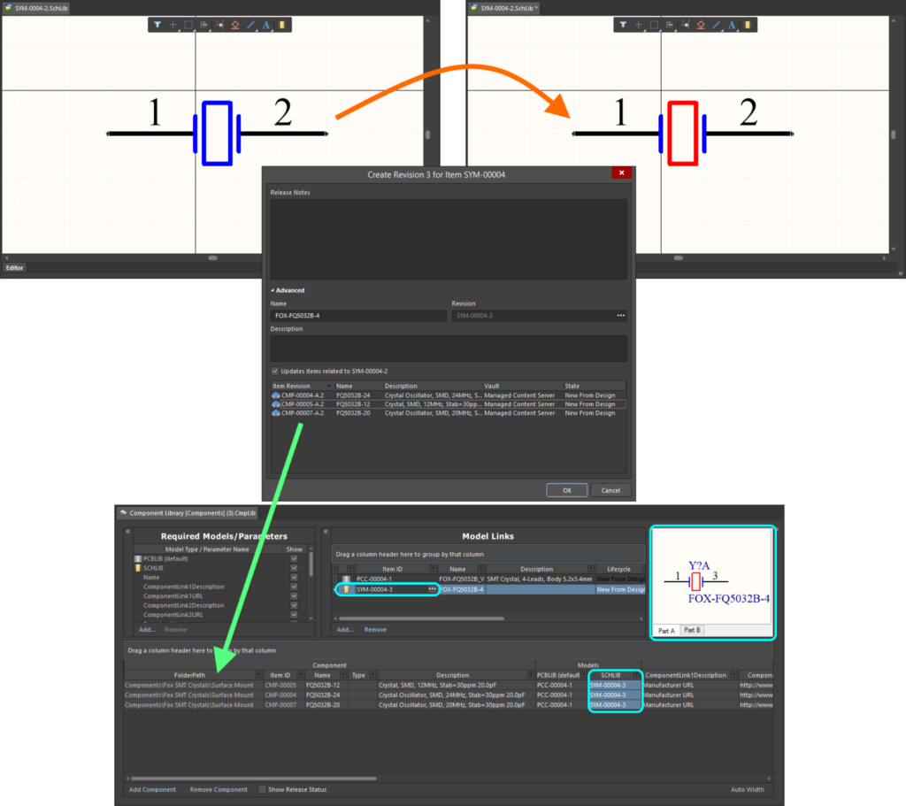
Therefore, when designing Component Connection Processing Graphic Symbol, most of the modular and parametric design methods are used to separate the electrical information, position information, etc. of the components from the component symbols.
The electrical component symbol library, and an electrical symbol can be used by different components, and the electrical information, position and other data information of the component are stored in the corresponding drawings during electrical design to reduce the workload of building the component symbol library.


