Analog Ground Plane Design in Cloning PCB
Sensitive analog components such as amplifiers and voltage references are always referenced and decoupled to the Analog Ground Plane Design in Cloning PCB. The ADCs and DACs (and other mixed-signal ICs) with low digital currents should generally be treated as analog components and also grounded and decoupled to the analog ground plane.
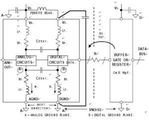
At first glance, this may seem somewhat contradictory, since a converter has an analog and digital interface and usually has pins designated as analog ground (AGND) and digital ground (DGND). The diagram shown in below Figure will help to explain this seeming dilemma.

Proper Grounding of Mixed-signal ICs with Low Internal Digital Currents
Inside an IC that has both analog and digital circuits, such as an ADC or a DAC, the grounds are usually kept separate to avoid coupling digital signals into the analog circuits when cloning PCB. Above Figure shows a simple model of a converter. There is nothing the IC designer can do about the wirebond inductance and resistance associated with connecting the bond pads on the chip to the package pins except to realize it’s there.
The rapidly changing digital currents produce a voltage at point B which will inevitably couple into point A of the analog circuits through the stray capacitance, CSTRAY. In addition, there is approximately 0.2 pF unavoidable stray capacitance between every pin of the IC package! It’s the IC designer’s job to make the chip work in spite of this.
However, in order to prevent further coupling, the AGND and DGND pins should be joined together externally to the analog ground plane with minimum lead lengths. Any extra impedance in the DGND connection will cause more digital noise to be developed at point B;
it will, in turn, couple more digital noise into the analog circuit through the stray capacitance. Note that connecting DGND to the digital ground plane applies VNOISE across the AGND and DGND pins and invites disaster!


