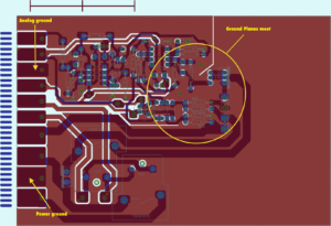
Even if the wiring pattern and layout drawing in the entire PCB board Gerber file is completed well, the interference caused by the inconsistency of the power supply and the ground line may degrade the performance of the product, and sometimes even affect the success rate of the product.
Therefore, the Circuitry Pattern of electricity and ground wires should be taken seriously when Clone PCB Board, and the noise interference generated by electricity and ground wires should be minimized to ensure the quality of the products.
For every Clone PCB Board engineer engaged in the design of electronic products, the reason for the noise between the ground and the power line is understood. Only the reduced noise suppression is described:
It is well known to add a decoupling capacitor between the power supply and the ground.
Try to widen the power supply and ground line width. It is better to ground the ground line than the power line. Their relationship is: ground line > power line > signal line. Usually the signal line width is 0.2~0.3mm, and the finest width is up to 0.05 to 0.07 mm, power cord is 1.2 to 2.5 mm.

Clone PCB Board Power Supply and Ground Line Circuitry Pattern
when Clone PCB Board with the digital circuit, a wide ground wire can be used to form a loop, that is, a ground net is used for use (the ground of the analog circuit cannot be used in this way), Use a large area of copper for grounding, and connect the unused areas to the ground on the printed board for grounding. Or make a multi-layer board, power supply, ground line each occupy a layer.


