Clone Electronic PCB Board Schematic Diagram needs to know how to draw it in a proper way, as we all know the quantity of resistor, capacitor, inductor and magnetic bead are count for the most in the electronic components of a Printed circuit board assemblies;
RESISTOR:
As shown in below figure, write resistance and accuracy for each resistor. For high-power resistors, power can also be written, and it should be flexible depending on the specific situation.

How to specify resistor on the Electronic PCB Board Schematic Diagram
Generally, the sampling resistance on the switching power supply and the resistance on the operation and discharging circuit have to use 1% accuracy, and the pull-up and pull-down resistors can use 5% accuracy.
Note: The resistance value here is not recommended to be written as 102, it should be written directly as 1K. Try not to let others do this conversion, or they won’t do it.

How to specify capacitor on the cloned Electronic PCB Board Schematic Diagram
As shown in the figure above, each capacitor has its capacitance value and withstand voltage written on it. For high-precision capacitors, you can also write accuracy or material. For example, the materials of ceramic capacitors are X7R, Y5V, NP0, etc. Note: The capacitance value here is not recommended to be written as 105, it should be written directly as 1uF.

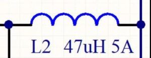
Write inductance value and saturation current for each inductor
Write inductance value and saturation current for each inductor.

Write the resistance value and the corresponding frequency on each magnetic bead
Write the resistance value and the corresponding frequency on each magnetic bead.


