As for open source hardware Circuit board, one of the most important point is the open schematic diagram, through schematic diagram, we can know the input and output of a module, as well as the integrated circuit type applied on it as well as other information related to it. so we have to learn Circuit Board Schematic Reading tips:
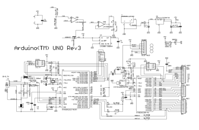
Below is the schematic diagram of ARDUINO UNO R3,
Circuit Board Schematic Reading can be proceed from below aspects:
1st Recognize the components;
2nd trace the circuit tracks;
3rd Understand the schematic diagram;
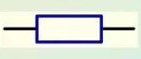
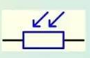
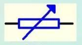
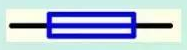
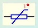
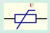
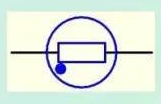
First of all is to recognize the components, let’s discuss the resistors, there are a great amount of resistors on the circuit board schematic diagram, below are several kinds of resistors:
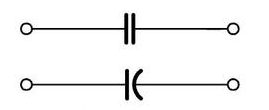
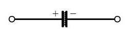
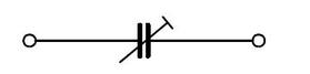
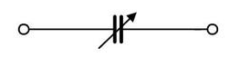
The capacitor is divided into a common fixed capacitor, an electrolytic capacitor with positive and negative polarity, and a tantalum capacitor. There are also variable capacitors commonly used in radios. General PCB Board schematic diagram will use C to indicate: