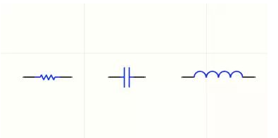
A complete Circuit Board Schematic Diagram is indispensable for the presence of passive components such as resistors, capacitors, inductors, and so on. The pattern of their schematic packaging is basically fixed: two horizontal lines + small symbols, these are the conventions.
How to judge passive devices? Passive devices only require input signals and can operate without an external power supply. In addition to the input signal, the active device must have an external power supply to work properly.

The schematic package of simple components will be drawn, so what should we do with more complex components? For example, the CPU of the Intel LGA1151 interface has more than a thousand pins, and the schematic package for manually drawing such chips is really prohibitive. At this point, you can try to get the schematic package compatible with the EDA tool format you are using from the integrated circuit manufacturer, or use some auxiliary gadgets.
For example, Altium Designer software has a built-in schematic package drawing tool based on OCR (Optical Character Recognition) technology, which can automatically extract the pin name part of the integrated circuit data sheet and copy the name into the package. You don’t have to type words one by one which will bring great convenience for either PCB design or PCB Reverse engineering.


