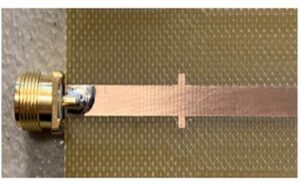
Characteristic Impedance Design in PCB Board Cloning is unchanged, the distance between the signal line and the reference layer must be increased while increasing the line width. Therefore, the surface radio frequency line of cloning pcb circuit card needs to refer to the third layer in the inter-layer, and the radio frequency is routed on the surface layer.

Characteristic Impedance Design in PCB Board Cloning
The second layer below the line is hollowed out. The PCB stacks that are used more in work are 12-layer, 8-layer and 6-layer, and some have encountered more than 20 layers. Generally speaking, in larger companies, PCB Layout and schematic design are done by different people, but this does not mean that hardware engineers do not need to understand PCB related knowledge,

it is best for the hardware engineer to indicate the points of attention when the signal is in the process of cloning circuit board layout on the schematic diagram
On the contrary, many times Layout engineers It is not clear which signals on the printed circuit board are the most important and which are the second. Therefore, it is best for the hardware engineer to indicate the points of attention when the signal is in the process of cloning circuit board layout on the schematic diagram, and actively communicate with the layout engineer to point out the problem points to assist in their changes. This requires hardware engineers to be more aware of the knowledge points related to electronic PCB circuitry scheme reLayout in order to provide effective guidance.


