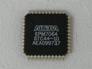
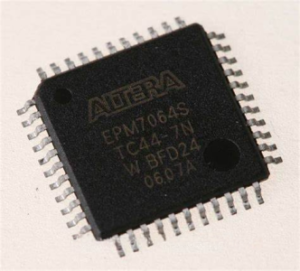
Break Altera CPLD EPM7064STC44-10 Eeprom Code and then retrieve IC Altera CPLD EPM7064STC44-10 eprom firmware, the multilayer printed circuit board schematic diagram on which the epm7064stc44 has been mounted will be reverse engineered;

Break Altera CPLD EPM7064STC44-10 Eeprom Code and then retrieve IC Altera CPLD EPM7064STC44-10 eprom firmware, the multilayer printed circuit board schematic diagram on which the epm7064stc44 has been mounted will be reverse engineered;
Pull-up resistors, series diodes and capacitors on the PGECx and PGEDx pins are not recommended as they will interfere with the programmer/debugger communications to the device. If such discrete components are an application requirement, they should be removed from the circuit during programming and debugging.
For device emulation and pcb card production reverse engineering, ensure that the “Communication Channel Select” pins (i.e., PGECx/PGEDx) programmed into the device match the physical connections for the ICSP to the Microchip debugger/emulator tool. For more information on available Microchip development tool connection requirements, refer to 28. Development Support.
Many microcontrollers have options for at least two oscillators: a high-frequency Primary Oscillator and a low- frequency Secondary Oscillator (refer to 9. Oscillator Configuration for details).

разбейте код eeprom Altera CPLD EPM7064STC44-10, а затем извлеките прошивку eprom IC Altera CPLD EPM7064STC44-10, принципиальная схема многослойной печатной платы, на которой был смонтирован epm7064stc44, будет реконструирована;
The oscillator circuit should be placed on the same side of the board as the device. Place the oscillator circuit close to the respective oscillator pins with no more than 0.5 inch (12 mm) between the circuit components and the pins. The load capacitors should be placed next to the oscillator itself, on the same side of the board.
Use a grounded copper pour around the oscillator circuit to isolate it from surrounding circuits. The grounded copper pour should be routed directly to the MCU ground. Do not run any signal traces or power traces inside the ground pour. Also, if using a two-sided board, avoid any traces on the other side of the board where the crystal is placed.


