Some function settings hidden in Altium Designer’s Preference for PCB Board Cloning, use these settings to make your PCB Layout design look clearer, clearer, and design drawing cloning more handy. There are many items on the tabs in the Preference dialog box. Today, let’s talk about the schematics.

Some function settings hidden in Altium Designer’s Preference for PCB Board Cloning, use these settings to make your PCB Layout design
There are many items on the tabs in the Preference dialog box. Today, let’s talk about the SCH.
There are many functions, and some of us may encounter such a situation, that is, we know the words at all, but when combined into one function, we don’t know what it is for.
Here we extract a few functions to explain, after explaining it, everyone will be able to understand how to use it.
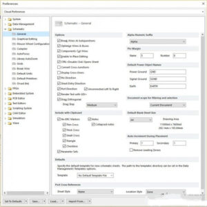
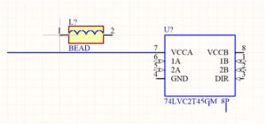
1. Components cut wires This is used to set when a component is placed on a wire, the wire will be automatically divided into two sections, and the two ends are connected with the component. (Note that this option can be checked only after checking “optimize wires&buses”)
Hereby check below reference:


The suffix of the component subsection has been changed.
3. Default blank sheet size is the default blank sheet size setting option. Before the engineering design, you can set the duplicated printed circuit board drawing according to your own needs, so as to avoid the phenomenon that the drawing size is found to be inappropriate and hurriedly modified in the later process.
4. Auto-Increment During Placement
Among them, primary is used to set the component number to automatically increase according to the set value when the same component is placed twice on the schematic diagram of printed wiring board; secondary is used to automatically increase the pin number when editing the component library;
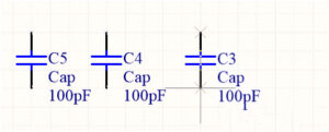
Note that a positive number here means increase, and a negative number means decrease by value, as shown in the below figure:


