Decoupling Capacitor Role in PCB Board Gerber Redesign, from the circuitry design point of view, it can always be divided into the source of the drive and the load being driven.

Decoupling Capacitor Role in PCB Board Gerber Redesign
If the load capacitance is relatively large, the drive circuit must charge and discharge the capacitance to complete the signal jump. When the rising edge is relatively steep, the current is relatively large, so that the drive current will absorb a large power supply current. The inductance and resistance (especially the inductance on the chip pins will bounce).
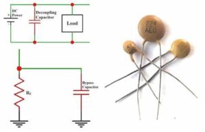
Compared with the normal situation, this current is actually a kind of noise, which will affect the normal operation of the previous stage. This is the so-called “coupling”. The decoupling capacitor acts as a “battery” to meet the change of the drive circuit current and avoid mutual coupling interference.

The decoupling capacitor acts as a “battery” to meet the change of the drive circuit current and avoid mutual coupling interference
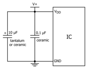
Combining bypass capacitors and decoupling capacitors will make it easier to understand. The bypass capacitor is actually decoupled, but the bypass capacitor generally refers to high-frequency bypass, that is, to improve a low-impedance leakage prevention method for high-frequency switching noise.
High-frequency bypass capacitors are generally relatively small, generally 0.1UF, 0.01UF, etc. according to the resonance frequency; while the capacity of decoupling capacitors is generally larger, which may be 10UF or greater, depending on the distribution parameters in the circuit and the drive.
The current change size is determined. Bypass is to take the interference in the input signal as the filtering object, and decoupling is to take the interference of the output signal as the filtering object to prevent the interference signal from returning to the power supply. This should be their essential difference.


