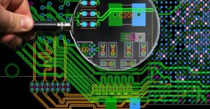
In terms of environment, the Pad Geometry Design in PCB Reverse Engineering may be different and it is based on the type of welding used to mount the electronic parts. When it becomes possible, the pad shape should be defined in a way that is transparent to the mounting process used.
Whether the parts are mounted on one or both sides of the PCB board, subjected to wave soldering, reflow soldering, or other methods, the pad and part dimensions should be optimized to ensure proper solder joints and inspection criteria.

Pad Geometry Design in PCB Reverse Engineering
Although the soldering patterns are dimensionally defined, and because it is part of geometry shape of printed circuit board, they are limited by the level of producibility and the tolerances associated with plating, corrosion, assembly, or other conditions.
When Installing the socket for BGA component, the geometrical shape of the soldering pad and fixed socket are normally round, and through the adjustment of the diameter can satisfy the change of distance among the contact point. And the diameter of soldering pad should not greater than the contact points on the package, and it will normally has 10% smaller than the regulated ball.
Before the final decision of the geometrical shape and soldering pad array after Pad Geometry Design in PCB Reverse Engineering, take IPC-SM-782 or the manufacturer regulation as the reference, and there two ways will be applied to define the fixed socket: define the soldering pad or copper and the solder resistance mask definition.
The soldering PAD of BGA can be shaped through the chemical erosion, no solder resist layer or solder resist overlay on the soldering pad copper track to define the pattern of the soldering pad —- the distance of soldering resistance must be at least 0.075mm. for those PCB reverse engineering with less distance than this reference value should consult the PCB board manufacturer before go into mass production;


