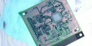
PCB Board Reverse Engineering Dimensional Analysis objective refers to the electronic/mechanical components on the Printed circuit board, the dimensions define the size and shape of the part and locate all part features.
Tolerances describe the dimensional limits to facilitate manufacturing while ensuring proper fit and function of parts or assemblies. A dimensional analysis should be conducted on all electronic/mechanical piece-parts/components. Parts that could not be disassembled previously may be cross-sectioned and cut away if necessary to establish the dimensional data.

PCB Board Reverse Engineering Dimensional Analysis
Considerations
The following should be considered when performing the PCB Board Reverse Engineering Dimensional Analysis:
1st is Bearing housings and shaft fits should be noted. When they are not in accordance with standard recommended practices in the bearing manufacturer’s catalog, additional bearing seats and tolerances should be reviewed and investigated. The variation could be a manufacturing error or done deliberately for some engineering purpose.
2nd is Assumptions concerning screw threads should be avoided since manufacturers often produce unique threads to prevent others from copying them or substituting standard threaded parts. The pitch diameter should be measured and compared to the classes provided in Federal Standard H28/18.
3rd is All clearances should be measured and noted to assist in the tolerance of individual parts. These should include, but are not limited to:
(1) Lateral movement,
(2) Backlash (gears and splines).
(3) Torque,
(4) Operating loads (i.e., handles), and
(5) Keyway clearances.


