LVDS Output on Multi-Function Recorder PCB Reverse Engineering
LVDS Output on Multi-Function Recorder PCB Reverse Engineering for high performance ADCs should be treated differently than standard LVDS outputs used in digital logic. While standard LVDS can drive 1 meter to 10 meters in high speed digital applications (dependent on data rate), it is not recommended to let a high performance ADC drive that distance.
It is recommended to keep the output trace lengths short (< 2 in.), minimizing the opportunity for any noise coupling onto the outputs from the adjacent circuitry, which may get back to the analog inputs. The differential output traces should be routed close together, maximizing common-mode rejection, with the 100 Ù termination resistor close to the receiver.
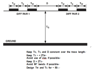
Users should pay attention to PCB trace lengths to minimize any delay skew. A typical differential microstrip PCB trace cross section is shown in Below Figure along with some recommended layout guidelines.

Microstrip PCB Layout for Two Pairs of LVDS Signals
LVDS also offers some benefits in reduced EMI. The EMI fields generated by the opposing LVDS currents tend to cancel each other (for matched edge rates). In high speed ADCs, LVDS offers simpler timing constraints compared to demultiplexed CMOS outputs at similar data rates. A demultiplexed data bus requires a synchronization signal that is not required in LVDS. In demuxed CMOS buses, a clock equal to one-half the ADC sample rate is needed, adding cost and complexity, that is not required in LVDS.


