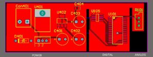
Restore PCB Board to Separate Analog and Digital Grounds
As a fact of life, digital circuitry is noisy. Saturating logic, such as TTL and CMOS, draws large, fast current spikes from its supply during switching. However, logic stages, with hundreds of millivolts (or more) of noise immunity, usually have little need for high
levels of supply decoupling which can play important role on Restore PCB Board to Separate Analog and Digital Grounds.
On the other hand, analog circuitry is quite vulnerable to noise on both power supply rails and grounds. So, it is very sensible to separate analog and digital circuitry, to prevent digital noise from corrupting analog performance. Such separation involves separation of both ground returns and power rails, which is inconvenient in a mixed signal system.
Nevertheless, if a mixed signal system is to deliver full performance capability, it is often essential to have separate analog and digital grounds, and separate power supplies. The fact that some analog circuitry will “operate” (i.e., function) from a single +5 V supply does not mean that it may optimally be operated from the same noisy +5 V supply as the microprocessor and dynamic RAM, the electric fan, and other high current devices!
What is required is that the analog portion operate with full performance from such a low voltage supply, not just be functional. This distinction will by necessity require quite careful attention to both the supply rails and the ground interfacing.
Note that analog and digital ground in a system must be joined at some point (the star ground concept), to allow signals to be referred to a common potential. This star point, or analog/digital common point, is chosen so that it does not introduce digital currents into the ground of the analog part of the system—it is often convenient to make the connection at the power supplies.


