The Electrical Component in PCB Board CAD Design Reverse Engineering contain electrical information, positional information, and graphical geometric information. The electrical information includes the name, type of code, manufacturer, voltage, current, etc. of the electrical component.

The position information indicates the position of the component in the drawing. The graphic information includes the shape of the symbol, the number of pins, and the position of the pin.
However, the electrical symbol is the basic element of the electrical component. The important information is its graphic shape. In the relevant national standards, the drawing of different types of electrical symbols, the meaning of electrical symbols, and the use of electrical symbols are all with clear provisions.
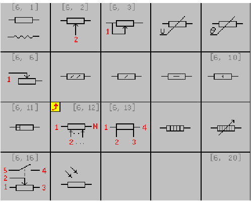
There are many types of electrical components, such as resistors, protectors, sockets, capacitors, inductors, diodes, switches, triodes, meters, and so on. There are many graphical symbols in each class. For example, the resistance class has several types as shown in the below figure:

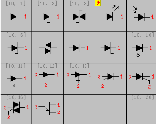
And the diodes are shown in the following types:

It can be seen that there are many symbols of circuit components. If the symbol of a component is judged according to a certain component model, and then the corresponding graphic symbol is selected, the operation will be a waste of time. Electronic component graphic symbols are composed of basic graphic elements such as lines, arcs, filled blocks, and text. In most CAD software, the component processing method is to arrange a component and graphically represent it with its corresponding standard electronic component symbol. The method is: classify electrical components, each class lists its circuit symbols, when a component is to be arranged, first select a certain component, and then select its corresponding component graphic symbol.


